
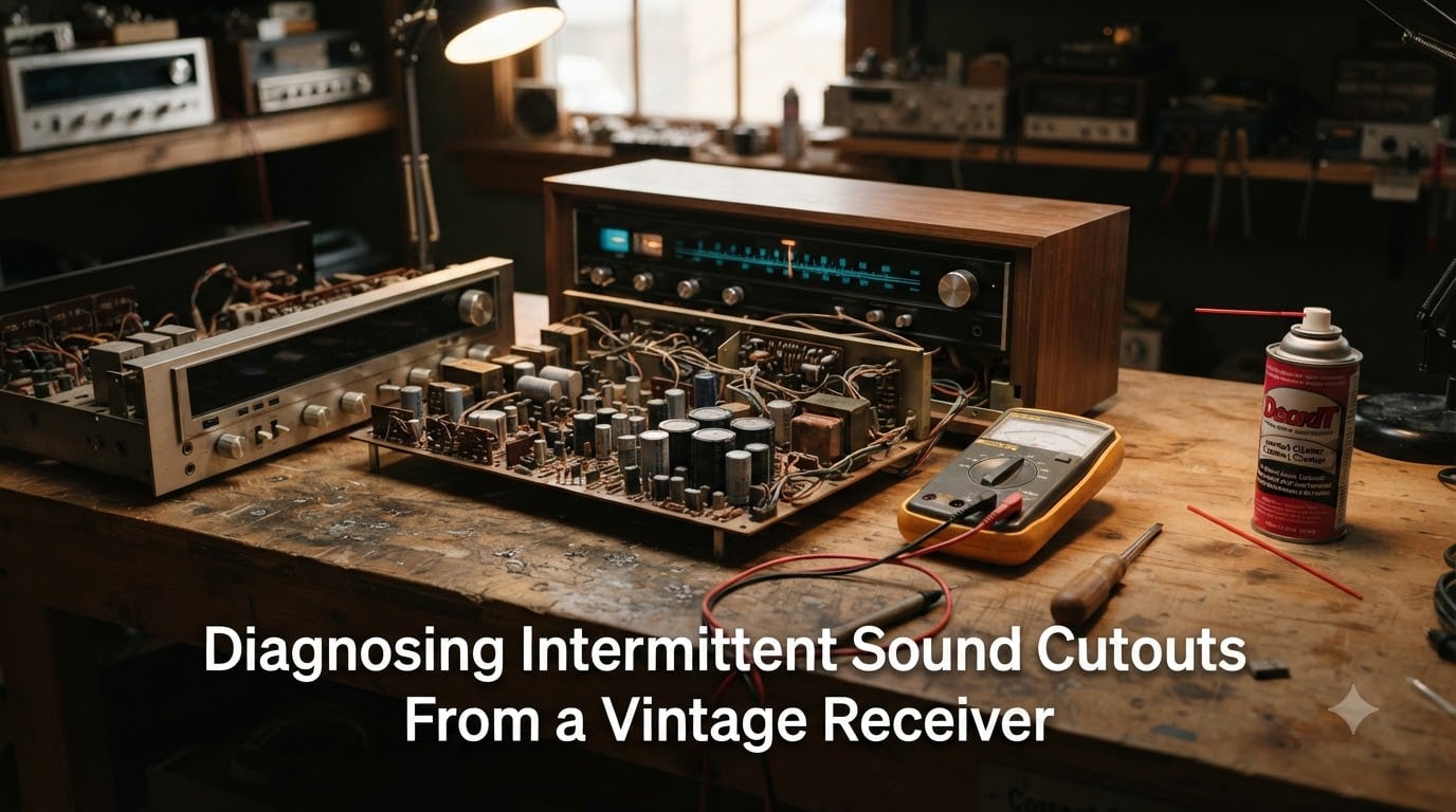
There is nothing quite like the warm sound of a vintage receiver filling the room. Until, without warning, the left channel goes silent for ten seconds, crackles back to life, then drops out again. If you are here, you already know the frustration of diagnosing intermittent sound cutouts from a vintage receiver. The good news is that most cutouts trace back to a handful of common failures, and you can isolate them without expensive lab equipment.
This guide walks you through a systematic diagnostic process I have refined over years of repairing classic stereo gear from the 1970s and 1980s. We will cover safety first, then work through every likely cause from the simplest cable swap to measuring DC offset and testing capacitors with an ESR meter. By the end, you will know exactly what to check and in what order.
Vintage receivers are absolutely worth repairing. Many enthusiasts prefer the build quality and sound character of classic Marantz, Sansui, Pioneer, and Technics units over modern equivalents. A methodical approach saves you from replacing parts blindly and gets your music flowing again.
Table of Contents
Safety Precautions Before You Begin
Before opening any receiver, understand that the power supply section contains large electrolytic capacitors that can hold dangerous charge for minutes or even hours after the unit is unplugged. A charged cap in a 40-year-old receiver can deliver a shock that stops your heart. Safety is not optional here.
Always unplug the receiver from the wall before removing the cover. Once the case is open, use a resistor (about 2.2k ohm, 5 watt) with insulated leads to discharge the main filter capacitors. Touch one lead to the positive terminal and the other to the chassis ground, then hold for several seconds. Verify with your multimeter that the voltage has dropped below 10 volts before touching anything inside.
If you plan to test the receiver while the cover is off, use an isolation transformer. This device isolates the receiver from mains ground and prevents a potentially lethal current path through your body to ground. A variac combined with an isolation transformer is the gold standard for bench work.
Follow the one-hand rule when probing a live circuit. Keep one hand behind your back or in your pocket. This prevents current from flowing across your chest if your other hand accidentally touches a live point. It sounds simple, but this habit has saved countless technicians.
Wear safety glasses when soldering or desoldering components. Hot flux can spatter, and old solder connections sometimes release debris when heated. Keep a fire extinguisher nearby, and never work on electronic equipment on a damp floor or near water.
Tools You’ll Need for Diagnosis
You do not need a full electronics lab, but a few tools make diagnosis far more efficient. Here is what I keep on my bench:
Digital multimeter with DC voltage, resistance, and continuity modes
ESR meter for testing electrolytic capacitors in-circuit
Contact cleaner such as DeoxIT D5 for switches and potentiometers
Soldering iron (40-60 watt) with rosin-core solder and a desoldering pump
Service manual or schematic for your specific receiver model
Isolation transformer for safe live-circuit testing
Alligator clip leads for making temporary connections
Isopropyl alcohol (99 percent) for cleaning board residue
If you do not have an ESR meter or isolation transformer yet, you can still work through most of this guide. Start with the non-invasive steps and invest in those tools as your repair skills grow.
Common Causes of Intermittent Sound Cutouts
Intermittent sound cutouts in vintage receivers almost always come from one of these six sources. I have ranked them roughly by how frequently I encounter them in the shop:
Dirty switches and potentiometers – Oxidation builds up on the contacts of the source selector, tape monitor, loudness switch, and volume pot over decades. This is the single most common cause of crackling and dropouts.
Failing electrolytic capacitors – Electrolytic paste dries out over time, changing the capacitor’s value and equivalent series resistance. Power supply caps are especially prone to this.
Cold or cracked solder joints – Thermal cycling over decades causes solder joints to micro-fracture. Connections on the output board and power supply are common culprits.
Faulty output transistors – When a transistor in the output stage begins to fail, it can cut out under thermal stress or load. This often affects one channel.
Protection relay issues – The relay contacts oxidize, or the relay triggers intermittently due to fluctuating DC offset. You will hear a clicking sound when this happens.
Bad cables and input jacks – Dirty AUX inputs, worn RCA jacks, and faulty 3.5mm adapters cause cutouts that mimic internal failures. Always rule these out first.
Forums like AudioKarma and r/vintageaudio consistently confirm this same hierarchy. Multiple users report that DeoxIT cleaning alone resolves a surprising percentage of intermittent cutout cases.
How to Identify the Problem Channel?
Before tearing into the receiver, isolate whether the problem is channel-specific, source-specific, or global. This five-minute test narrows your search dramatically.
First, swap the speaker wires at the back of the receiver. If the cutout moves to the other speaker, the problem is in the receiver’s amplifier section. If the same speaker continues to cut out, your speaker or speaker wire may be the issue.
Next, swap the left and right RCA inputs from your source. If the cutout follows the cable to the other channel, you have a bad cable or a dirty input jack. Try a different source entirely, like switching from AUX to a CD player or phono input, to see if the problem persists across sources.
If your receiver has a mono switch, engage it. In mono mode, both channels carry the same signal. If one channel still cuts out while the other plays fine, the fault is downstream of the mono blend circuit, pointing to the power amplifier section or output stage.
Take notes during this process. Write down exactly what happens with each swap. The pattern you uncover here determines which section of the receiver you focus on next.
Step-by-Step Troubleshooting Guide
Diagnosing intermittent sound cutouts from a vintage receiver follows a clear progression from the simplest checks to the most involved. Work through these steps in order, and do not skip ahead. Each step either fixes the problem or eliminates a category of faults.
Step 1: Rule out cables and external connections. Replace every cable between your source and receiver, and between the receiver and speakers. Use known-good spares. Wiggle each connector while music plays. If you hear crackling or the sound cuts out, that jack or cable needs attention. This single step resolves a surprising number of cases.
Step 2: Exercise every switch and control. With the receiver powered on at low volume, flip the source selector through every position twenty to thirty times. Do the same with the tape monitor, loudness, mono, high filter, and mode switches. Rotate every potentiometer, including volume, balance, bass, and treble, through its full range repeatedly. If exercising a switch temporarily fixes the cutout, that switch needs cleaning.
Step 3: Clean switches and potentiometers with DeoxIT. Unplug the receiver, open the case, and locate the potentiometers and rotary switches. Spray a small amount of DeoxIT D5 directly into the potentiometer body or onto switch contacts through any access hole. Work the control through its full range thirty times to spread the cleaner and scrape away oxidation. Let it sit for ten minutes before powering on. Repeat for every control, not just the one you suspect.
Step 4: Inspect all fuses. Locate every fuse on the circuit boards and in the power supply. Pull each one and measure its resistance with your multimeter set to the continuity or ohms range. A good fuse reads near zero ohms. A blown fuse reads open (infinite resistance). Replace any blown fuse with the exact same type and rating, never a higher rating. If a replacement fuse blows immediately, you have a short circuit downstream that needs further diagnosis.
Step 5: Measure DC offset at the speaker outputs. With the receiver powered on and no input signal, set your multimeter to DC volts. Connect the probes across the positive and negative speaker terminals for each channel. A healthy channel reads under 50 millivolts DC, ideally under 20 mV. A reading above 100 mV indicates a problem in the output stage, typically failing output transistors or driver circuitry. This measurement tells you whether the protection relay is doing its job or masking an underlying fault.
Step 6: Test capacitors with an ESR meter. Focus on the power supply filter capacitors first, as these carry the most stress. Discharge each cap before testing. Place the ESR meter probes across the capacitor and compare the reading to the chart that comes with the meter for that capacitance and voltage rating. A reading significantly higher than the reference value means the cap is failing. Bulging tops, leakage, or a domed vent pattern are visual confirmation of failure.
Step 7: Check the protection relay. Listen for relay clicking when the cutout occurs. If you hear the relay drop out and pull back in, the receiver is cycling its protection circuit. This means the amplifier is producing excessive DC offset or drawing too much current. Clean the relay contacts with a strip of paper soaked in isopropyl alcohol drawn between the closed contacts. If the relay itself is weak, replacement is straightforward.
Step 8: Inspect solder joints under magnification. Examine the output board, power supply board, and any connector headers under a bright light with a magnifier. Look for rings or cracks around solder pads, dull grainy joints, and pads lifting from the board. Resolder any suspicious joint with fresh rosin-core solder. Cold joints on transistor legs and connector pins are a frequent source of intermittent faults.
Step 9: Test output transistors. With the receiver unplugged and capacitors discharged, test each output transistor using the diode test function on your multimeter. Place the red probe on the base and the black on the collector, then swap. One direction should read about 0.6 to 0.7 volts (a normal PN junction). The reverse direction should read open. Repeat for the base-to-emitter junction. A short circuit in both directions or a dead-open reading indicates a failed transistor that needs replacement.
Cleaning Switches and Potentiometers
Dirty contacts are the number one cause of intermittent sound cutouts in vintage receivers. Decades of oxidation, dust, and atmospheric contamination build up on every metal-to-metal contact inside the unit. The good news is that proper cleaning fixes the majority of cases without any component replacement.
I use Caig DeoxIT D5 for switches and potentiometers, followed by DeoxIT FaderLube F5 for conductive plastic elements. The D5 dissolves oxidation, while the F5 leaves a protective film that prevents future buildup and lubricates the contact surfaces. Never use general-purpose WD-40 on electronics, as it leaves a residue that attracts dust and degrades signal quality.
The process is simple but requires patience. Spray a one-second burst of DeoxIT into the potentiometer body or onto the switch contact area. Then work the control through its full range of motion at least thirty times. You will often hear the crackling diminish as you exercise the control. Let everything dry for ten to fifteen minutes before powering up.
Pay special attention to the source selector switch and the tape monitor switch. These carry the audio signal through every listening session and accumulate the most oxidation. The tape monitor switch in particular is notorious for causing cutouts because it is often left in one position for years without being exercised.
For sliding contacts like those found in some source selectors, spray the cleaner onto the contact fingers and slide the switch back and forth repeatedly. For push-button switches, spray around the button shaft and press the button many times. Be thorough, because cleaning every control takes an hour but prevents repeat failures.
Capacitor Diagnosis and Testing
Electrolytic capacitors have a finite lifespan. The electrolyte paste inside them gradually dries out over twenty to thirty years, which means every vintage receiver is living on borrowed time with its original capacitors. When caps fail, they cause hum, distortion, channel imbalance, and intermittent cutouts.
Look for visual signs of failure first. A bulging top on the capacitor can is a clear indicator that internal pressure has built up from gas generation. Brown or crusty residue around the base of a capacitor indicates electrolyte leakage. A capacitor whose vents have blown open has failed catastrophically and must be replaced.
An ESR meter gives you a definitive test without removing the capacitor from the circuit. ESR stands for Equivalent Series Resistance, and it rises as an electrolytic cap ages and dries out. Compare the measured ESR against a reference table for the capacitor’s value and voltage rating. A reading two to three times higher than the reference means the cap is well on its way out.
Power supply filter capacitors are the most critical to check. These large caps smooth the DC voltage that feeds every amplifier stage. When they fail, ripple increases, and the entire audio path suffers. If you find one failed power supply cap, plan to replace all of them in that section, as they age at similar rates.
Protection Relay Behavior and Issues
The protection relay in a vintage receiver serves two purposes. It delays speaker connection at power-up by a few seconds while the amplifier stabilizes. It also disconnects the speakers if it detects excessive DC offset at the output, protecting your speakers from damage.
If you hear a relay click when the sound cuts out, the protection circuit is triggering. This means the amplifier is producing DC voltage on the output line, which the relay detects as a fault. The root cause is typically a failing output transistor, a leaky driver transistor, or an unstable bias circuit. The relay is doing its job, but the underlying fault needs repair.
Relay contacts themselves can also cause problems. Over decades of use, the contacts oxidize and pit. When the contacts are dirty, the audio signal passes through high-resistance connections, causing crackling and level drops. To test whether the relay contacts are the issue, gently tap the relay body with a plastic tool while music plays. If the sound responds, the contacts need cleaning or the relay needs replacement.
Cleaning relay contacts is a temporary fix. Use a strip of clean paper soaked in isopropyl alcohol, draw it between the closed contacts a few times, then repeat with dry paper. For a permanent solution, replace the relay with an equivalent part. This is a low-cost fix that eliminates an entire category of intermittent faults.
When to Use Service Documentation
A service manual for your specific receiver model is one of the most valuable tools you can have. It contains the schematic diagram, board layouts, component values, voltage charts, and adjustments specific to your unit. Without it, you are guessing at signal paths and test points.
You can find service manuals for most vintage receivers at sites like HiFi Engine, Vinyl Engine, and Elektrotanya. These are usually free PDF downloads. Search for your exact model number, including the suffix, as different regions sometimes have different versions.
The schematic shows you the signal path from input to output. When you know which switches, capacitors, and transistors the audio passes through, you can trace the signal methodically. The voltage chart lists expected DC voltages at key test points, which lets you compare your measurements against factory specifications.
Some receivers have well-documented common failure modes. The community at AudioKarma has compiled lists of known issues for popular models from Sansui, Marantz, Pioneer, and Technics. Searching for your model number plus “common problems” or “known issues” before you start can save hours of diagnosis time.
Frequently Asked Questions
Why does my audio intermittently cut out?
Intermittent audio cutouts are most commonly caused by dirty switches and potentiometers, failing electrolytic capacitors, cold solder joints, or faulty output transistors. Start by cleaning all switches and controls with DeoxIT contact cleaner, then measure DC offset at the speaker outputs to check the amplifier stage.
Why is my receiver cutting out?
If your receiver cuts out accompanied by a relay click, the protection circuit is triggering due to excessive DC offset at the output. This points to a failing output transistor, leaky driver transistor, or unstable bias circuit. Measure DC voltage at the speaker terminals with no signal; anything over 100 millivolts indicates an amplifier stage fault.
Do vintage stereo receivers sound better?
Many audio enthusiasts prefer vintage receivers for their build quality, discrete component design, and warm analog sound character. Units from the 1970s and 1980s from brands like Marantz, Sansui, and Pioneer are highly regarded. Their sound quality makes them well worth maintaining and repairing.
What causes one channel to cut in and out on a vintage receiver?
A single channel cutting in and out is typically caused by a dirty source selector or tape monitor switch, a failing coupling capacitor on that channel, a cold solder joint on the output board, or a faulty output transistor. Swap speaker wires and input cables first to confirm the problem is inside the receiver and not external.
Conclusion
Diagnosing intermittent sound cutouts from a vintage receiver comes down to a systematic, step-by-step approach. Start with the simplest checks like cable swaps and switch exercising, then move through DeoxIT cleaning, fuse inspection, DC offset measurement, and capacitor testing. Most cutouts resolve at the cleaning stage, but the deeper tests give you confidence when the problem is more involved.
The key is patience and method. Work through each step fully before moving to the next, keep notes on what you find, and use a service manual to guide your signal tracing. Vintage receivers were built to be serviced, and with the right approach, yours will be making music again for years to come.