
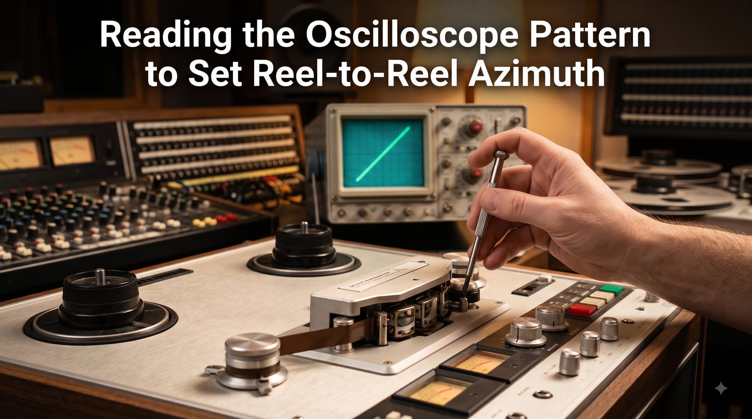
Reading the oscilloscope pattern to set reel-to-reel azimuth is the most accurate way to align your tape deck’s playback head. I have spent the last three years restoring vintage Studer and Otari machines, and the oscilloscope method remains the gold standard. This guide covers what you need, how to read the pattern, and what to do when things go wrong.
Azimuth is the angle between the tape head gap and the tape’s recorded track. When it is off, even by a fraction of a degree, your high frequencies suffer and the stereo image collapses. The oscilloscope gives you a visual, real-time look at the phase relationship between your left and right channels, which directly tells you whether your head is aligned.
Table of Contents
What Is Reel-to-Reel Azimuth and Why It Matters?
Reel-to-reel azimuth is the precise angle of the playback head’s gap relative to the tape’s recorded track. The ideal angle is exactly 90 degrees to the tape’s direction of travel. When the head is perfectly aligned, the recorded signal reaches both channels at the same time, producing identical waveforms.
Incorrect azimuth causes high-frequency loss called “azimuth loss.” A 0.5-degree misalignment at 15kHz can drop output by 6 dB. The audible result is muffled sound, rolled-off highs, and poor stereo imaging. Phase problems between channels also become apparent, especially when playing back material that was originally recorded with precise stereo placement.
For mastering engineers, archivists, and serious audiophiles, this matters because we are trying to recover what was on the original tape. A poorly aligned head throws away information that cannot be restored later through EQ. That is why I always check azimuth before any transfer work.
Understanding the Oscilloscope X-Y Mode
X-Y mode turns your oscilloscope into a two-dimensional display tool. Instead of plotting voltage against time, the scope plots channel 1 on the horizontal axis (X) and channel 2 on the vertical axis (Y). The result is a pattern that shows the phase relationship between two signals.
When two identical signals are perfectly in phase, the trace draws a straight diagonal line. The exact angle of that line depends on how the channels are connected. In azimuth work, a correctly aligned head produces a line inclined to the right (resembling “/”). An out-of-phase condition produces a line inclined to the left (resembling “”).
The slope of the line gives you additional information. A 45-degree angle means both channels have equal amplitude. A steeper line means one channel is louder than the other. When the head is misaligned, the line opens into an ellipse, and the ellipse gets wider as the misalignment increases.
Required Equipment and Setup
You need four things to set azimuth correctly: a two-channel oscilloscope, a calibration tape with an azimuth tone, a non-magnetic screwdriver sized for your head’s azimuth screw, and a quiet work environment. I use a Tektronix 2235 in my shop, but any scope with X-Y mode and at least 20 MHz bandwidth will work.
Your calibration tape should have an azimuth reference tone. MRL (Magnetic Reference Laboratory) tapes are the industry standard and provide multiple frequencies for different purposes. At minimum, you need 8 kHz for coarse adjustment and 16 kHz for fine adjustment. Some technicians also use 10 kHz at -10 dB for a quick sanity check.
Before you start, clean the playback head and guides. Oxidation and tape residue can leave deposits that shift the effective gap position. I clean with 99% isopropyl alcohol and a lint-free swab, then let everything dry for two minutes. A dirty head is the most common reason an otherwise correct adjustment gives inconsistent results.
How to Connect Your Oscilloscope to a Reel-to-Reel Deck?
Connect your scope probes to the deck’s left and right line outputs or monitor outputs. Most reel-to-reel machines have a switch on the back to select between fixed and variable output, and you want fixed for this procedure. The variable output is affected by the monitor level knob, which introduces unnecessary variables.
Set the scope to X-Y mode. On most Tektronix and Rigol scopes, this means pressing the X-Y button or selecting X-Y from the trigger menu. Channel 1 goes to the left audio output, and Channel 2 goes to the right audio output. If your scope has a “direct” or “AC” coupling switch, start with AC coupling to block any DC offset that might shift your pattern.
Set both channels to the same volts-per-division setting, typically 0.5V or 1V per division. Match your probe attenuation too. If you mix 10x and 1x probes, your pattern will have a wrong slope that can mislead you about channel balance. I keep a matched pair of probes taped together specifically for this job.
Frequency Selection: 8kHz Coarse vs 16kHz Fine
8 kHz is used for coarse azimuth adjustment because it is a longer wavelength that is more forgiving of small head height and tape path issues. The wavelengths are long enough that minor tape guide misalignment will not produce a false peak. You use this frequency to get into the right ballpark.
16 kHz is used for fine adjustment because it is much more sensitive to azimuth error. The wavelength at 16 kHz is roughly 19 micrometers, which is close to the actual gap width of many playback heads. Small errors that are invisible at 8 kHz show up clearly at 16 kHz. The trade-off is that 16 kHz is more sensitive to tape path problems, so you need the head height and tensions already dialed in.
On MRL calibration tapes, you typically find a section labeled “azimuth” or “head alignment” that steps through both frequencies. I always start at 8 kHz, lock the head close to peak, then fine-tune at 16 kHz. Running both frequencies back to back is also a good way to verify that your tape path is healthy. If 16 kHz peaks at a noticeably different azimuth than 8 kHz, you may have a tape path issue.
Reading the Lissajous Pattern: / Versus \
When azimuth is correctly set, the oscilloscope displays a line inclined to the right (a forward slash, “/”). This is the signature of two identical signals that are perfectly in phase. Many beginners expect a perfect 45-degree line, but the exact angle depends on your scope’s gain settings. What matters is that the line is straight and tilted to the right.
A line inclined to the left (a backslash, “\”) means your channels are 180 degrees out of phase. This usually happens when you have one probe polarity reversed, or when the head is more than a few degrees off. It does not mean the head is “wrong” in any absolute sense; it just means you need to rotate the head in the opposite direction.
An ellipse pattern indicates partial misalignment. The narrower the ellipse, the closer you are to correct. The wider the ellipse, the more adjustment is needed. As you rotate the azimuth screw, watch the ellipse collapse into a line. The moment it forms a clean line inclined to the right, you have hit the peak.
Rotate the screw slowly and watch the figure change. As you pass through the correct azimuth, the line flips direction. Between the two extreme inclinations, there is a narrow window where the pattern is a flat line. That flat spot is the precise azimuth peak. Listen for the audible change too. The high-frequency content will peak at the same point as the visual pattern.
Step-by-Step Azimuth Adjustment Procedure
Clean the playback head and tape path. Let it dry completely.
Connect the scope to the left and right outputs and set X-Y mode.
Load the calibration tape and cue the 8 kHz azimuth section.
Play the tape and observe the pattern shape and slope.
Loosen the azimuth lock screw if your deck has one. Do not fully remove it.
Insert the non-magnetic screwdriver into the azimuth adjustment screw.
Rotate the screw slowly until the ellipse collapses into a line inclined to the right.
Fine-tune by listening for the highest-pitched playback tone.
Stop the tape, switch to the 16 kHz section, and repeat the adjustment.
Re-lock the azimuth screw carefully and verify the pattern is still clean.
After locking, always recheck the pattern. Some screws can shift slightly when you tighten them. If the pattern moves, loosen, adjust slightly past the peak, then tighten while holding the screwdriver in place. This two-handed approach prevents the screw from rotating as you torque the lock.
Troubleshooting Common Pattern Problems
If your pattern is inclined to the left when you expect it to be on the right, the most common cause is reversed probe polarity. Swap the probes between channels and check again. If the pattern flips to the right, you have a probe issue, not a head issue. If it stays left, your head is rotated the wrong way.
A pattern that rotates around the screen as you adjust the screw means your azimuth is far from correct. The line is sweeping through every angle. This is normal during adjustment. The moment you pass through the in-phase point, the pattern will momentarily “stand still” as a line before continuing to rotate.
An unstable or jittery pattern usually points to a tape guidance issue. Check that the tape is seating properly against the head and that the tape tension is consistent. A fluttering tape will cause the pattern to wobble, making precise adjustment impossible. Fix the tape path first, then return to azimuth.
Two separate ovals instead of one connected pattern means your channels are reading completely different signals. This usually happens if the calibration tape is old or damaged, or if one channel of the head is shorted. Try a different section of the tape first. If the problem persists, the head itself needs service.
Gap Scatter and Its Effect on Stereo Heads
Gap scatter is the small mis-alignment between the left and right channel gaps inside a single stereo head. Manufacturing tolerances mean that the two gaps are not perfectly parallel. One channel’s gap may be tilted by a fraction of a degree relative to the other. This is normal and present in every stereo head, but the severity varies.
Gap scatter shows up as different azimuth peaks for the left and right channels. You may find that the left channel peaks at a slightly different screw position than the right channel. The correct compromise is the midpoint between the two peaks, where both channels are equally close to their own maximum. This is what technicians call the Optimum Read Head Azimuth, or ORA.
High-quality heads from manufacturers like Studer and Ampex have very small gap scatter, often less than 0.1 degrees. Cheap or worn heads can have much more, sometimes up to 1 degree. When gap scatter is severe, you cannot achieve perfect alignment on both channels simultaneously. You have to choose the compromise that minimizes overall high-frequency loss.
Calibration Tape Selection Guide
MRL (Magnetic Reference Laboratory) calibration tapes are the industry standard for professional tape deck alignment. They use precision recording equipment traceable to NIST standards and are available in multiple formats (1/4 inch, 1/2 inch, etc.) and tape formulations. The most popular for azimuth work are the 1/4 inch full-track and half-track standards.
Other options include older Ampex and Nortronics calibration tapes, which can still be found on the used market. These are acceptable but may have aged unpredictably. Tape formulation changes over time, and an old calibration tape may not give you the same result as when it was new. MRL tapes are still manufactured, which means you can buy fresh, accurate tapes today.
When buying a used calibration tape, always verify it against a known-good deck. Listen for clean tone without flutter or dropout. If you have access to a freshly calibrated machine, play the tape on it first and note the pattern. Any deviation from a clean line tells you the calibration tape itself is suspect.
VU Meter Alternative Method
If you do not have an oscilloscope, you can set azimuth using VU meters. Play the 8 kHz or 10 kHz calibration tone and watch both meters. Slowly rotate the azimuth screw until both meters reach their maximum deflection. The peak is narrow, so go slowly and use small movements.
This method works because maximum output corresponds to the head gap being centered over the recorded track. The VU meter reading is sensitive to a few tenths of a dB, which is enough to find the peak. The downside is that VU meters cannot distinguish between in-phase and out-of-phase conditions, so you might end up tuned to the wrong side of the peak.
To verify which side you are on, switch the tape to a stereo music recording with strong center-panned content (like vocals). If the VU meters drop slightly when you reverse the phase switch on your console, you are in phase. If they stay the same, you may be on the wrong side of the azimuth peak. Adjust until phase reversal causes a noticeable drop in level.
Frequently Asked Questions
What does the oscilloscope pattern look like when azimuth is correctly set?
A correctly set azimuth produces a straight line inclined to the right (resembling /) on the oscilloscope in X-Y mode. This line indicates that both channels are receiving identical signals in perfect phase. The exact angle depends on your scope settings, but the line should be straight, not elliptical.
What frequency should I use for azimuth alignment on a reel-to-reel?
Use 8 kHz for coarse adjustment and 16 kHz for fine adjustment. The lower frequency is more forgiving of tape path issues and gets you in the right range. The higher frequency is much more sensitive to small azimuth errors and lets you peak the adjustment precisely. MRL calibration tapes include both frequencies in their azimuth sections.
Why is my Lissajous pattern inclined to the left instead of right?
A left-inclined pattern (resembling u005c) means your channels are 180 degrees out of phase. The most common cause is reversed probe polarity on your oscilloscope. Swap the probes between channels and recheck. If the pattern still leans left, your head is rotated in the wrong direction and needs to be turned the other way.
How do I connect an oscilloscope to a reel-to-reel tape deck?
Connect the scope probes to the deck’s left and right line outputs (fixed, not variable). Set the scope to X-Y mode, with Channel 1 on the left output and Channel 2 on the right output. Use AC coupling to block DC offset, set both channels to the same volts-per-division, and use matched probes to maintain correct slope.
What is the difference between coarse and fine azimuth adjustment?
Coarse adjustment uses 8 kHz, a longer wavelength that tolerates small tape path variations and gets you close to the correct azimuth quickly. Fine adjustment uses 16 kHz, a much shorter wavelength that reveals fractional errors invisible at lower frequencies. Always start with coarse, then refine with fine for the best result.
Final Thoughts on Reading the Oscilloscope Pattern to Set Reel-to-Reel Azimuth
Reading the oscilloscope pattern to set reel-to-reel azimuth is a skill that pays off every time you play a tape. The method is fast, accurate, and repeatable once you understand what the pattern is telling you. Start with a clean head, a fresh calibration tape, and patient adjustment at both 8 kHz and 16 kHz.
Once you have done it a few times, the whole process takes under five minutes. Your tapes will sound noticeably better, and you will have confidence that you are hearing what was originally recorded. For 2026, the oscilloscope method remains the clearest way to verify what your ears already suspect.