
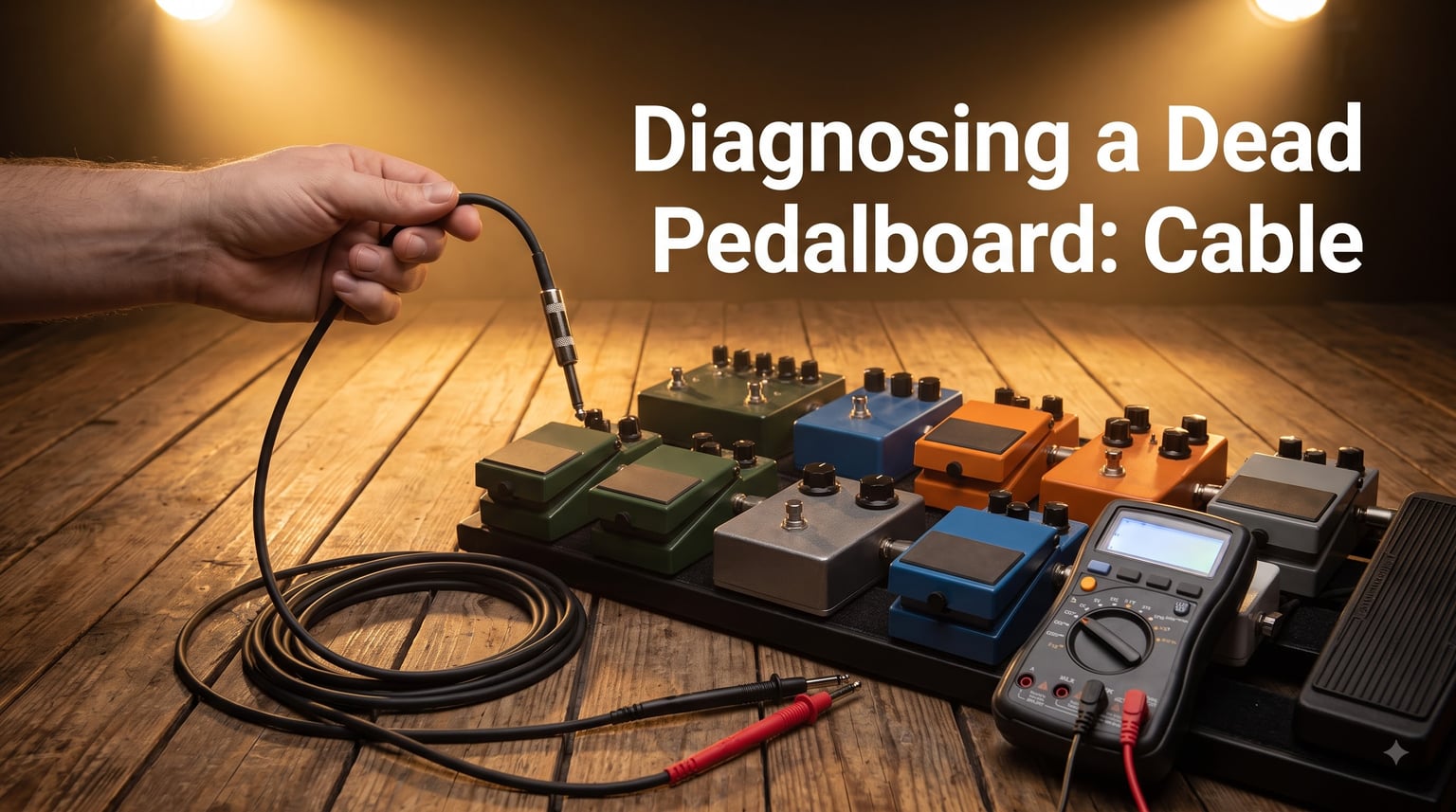
I have lost count of the number of times I have watched a guitarist stare at a silent amp for 20 minutes, swap pedals in every combination, blame the power supply, and only then discover the real culprit was a single dead patch cable hiding in plain sight.
This guide is the shortcut. I will show you exactly how to go from “zero sound, no idea why” to “found the cable in under five minutes” using a binary search method, a multimeter, and a few visual checks. Diagnosing a dead pedalboard cable is not magic – it is a repeatable sequence of steps anyone can learn.
I pulled the technique together after reading a Reddit thread where a player spent three hours hunting down one faulty true bypass cable. Three hours is too long. Let us make your next repair session take fifteen minutes instead.
Table of Contents
Signs and Symptoms of a Dead Pedalboard Cable
The fastest diagnosing a dead pedalboard cable troubleshooting starts with listening. A failing cable almost always announces itself before it goes silent. Here is what to listen for during your next practice session.
Complete silence: You plug in, hit a chord, and nothing comes out. Every pedal lights up but no signal reaches the amp.
Crackling and popping: Random snaps, pops, or static that appears when you move your foot or wiggle cables.
Intermittent cutouts: Signal drops in and out unpredictably, often returning when you touch or shift the board.
Tone loss or thin sound: The signal comes through but sounds weak, dull, or stripped of high frequencies.
Hum and buzz that gets louder when you touch a cable: A bad shield inside the cable lets interference leak in.
Signal works only at certain pedal angles: The cable makes contact in one position but loses it when you shift the pedal.
If you hear any of these symptoms, the cable is the prime suspect. In a true bypass pedal chain, one bad cable can knock out your entire rig with zero warning.
Quick Visual Inspection Checklist Before Any Testing
Before you reach for a multimeter, spend two minutes looking at the cables themselves. Most failures leave visible evidence if you know where to look.
Step 1 – Check the connector ends. Look for bent, pushed-in, or loose tip pins on each 1/4 inch plug. A pushed-in tip pin is the single most common patch cable failure I see on touring boards.
Step 2 – Inspect the cable jacket. Look for kinks, flat spots, crushed sections, or exposed shielding. A cable that has been stepped on once is usually a cable that needs replacing.
Step 3 – Wiggle test each end. With your guitar plugged in and a pedal active, gently wiggle the plug where it enters the connector barrel. If the signal cuts in and out as you wiggle, the joint inside that plug is failing.
Step 4 – Check solder joints at any DIY cables. A hairline crack in a solder joint looks like a thin dark ring around the connector pin. This is repairable but only if you catch it early.
Step 5 – Look at routing. Cables pinched between pedals or running under heavy power supplies fail faster than cables that sit in gentle curves.
Step-by-Step Troubleshooting Method for Finding the Bad Cable
When you have a dead pedalboard and you cannot tell which cable is bad, do not test one cable at a time. Use the binary search method instead – it cuts your troubleshooting time in half with every swap.
Step 1 – Identify the midpoint of your signal chain. Count your patch cables and find the cable that sits in the middle of the chain from input to output.
Step 2 – Swap that midpoint cable with a known-good spare. If the dead signal appears now, the problem was upstream of that cable. If signal returns, the problem was downstream.
Step 3 – Repeat on the suspect half. Keep halving the suspect section until you have isolated the single bad cable.
Step 4 – Confirm the diagnosis by swapping the suspect cable back in. The signal should die again. If it does, you have found your culprit.
Step 5 – Test the spare cable you used as a replacement to make sure it is healthy before relying on it for a gig.
This binary search method works because each step eliminates half the remaining possibilities. On a board with eight patch cables, you should find the dead one in three swaps instead of eight individual tests. A touring tech I know calls this “halving the chaos” and it has saved me on more than one soundcheck.
If you do not have a spare cable, the same method works by unplugging the suspect cable and bridging the gap with a finger on the input jack – just touch the tip of the jack briefly to confirm the upstream signal is alive.
How to Test Patch Cables with a Multimeter?
A multimeter is the most accurate way to confirm a cable is dead before you throw it away. Set your meter to continuity mode (the symbol that looks like a sound wave or diode) and follow this sequence.
Step 1 – Set the multimeter to continuity test mode. If your meter does not have a continuity setting, use the lowest resistance range, typically 200 ohms.
Step 2 – Touch the two probes together to confirm the meter beeps or shows 0 ohms. This proves the meter is working before you test the cable.
Step 3 – Place one probe on the tip of one end of the cable and the other probe on the tip of the opposite end. A healthy cable shows a reading between 0.0 and 0.5 ohms and beeps on continuity mode.
Step 4 – Repeat with the probe on the sleeve (the long metal shaft) of each end. A healthy sleeve connection reads the same low resistance and beeps.
Step 5 – Test for a short. Place one probe on the tip of one end and the other probe on the sleeve of the same end. The meter should show infinite resistance or “OL” – no beep. If it beeps, the cable is shorted internally.
Reading interpretation: 0.0 to 0.5 ohms means the cable is good. Any reading above 1 ohm or no beep means the conductor is broken inside. A beep when testing tip to sleeve means the cable has an internal short and must be replaced.
Most patch cable failures show up as an open circuit – no beep, no continuity – because the internal copper conductor has snapped from repeated flexing. This is why the wiggle test matters: the broken ends touch sometimes, giving you that maddening intermittent behavior.
True Bypass vs Buffered Pedal Cable Failure Modes
True bypass and buffered pedalboards fail in different ways, and recognizing which type of board you own changes how you diagnose a dead cable.
On a true bypass pedalboard, the guitar signal passes directly through each patch cable with no buffering. This means a single dead cable breaks the entire chain. The good news is binary search works perfectly here because every cable is a potential point of failure.
On a buffered pedalboard, one or more pedals have active electronics that rebuild the signal. A dead cable between buffered stages is easier to isolate because you can hear signal at each buffered output point.
True bypass systems have a hidden trap: intermittent cables that work when cold but fail when warm. Heat from stage lights or summer gigs can expand a cracked solder joint just enough to break contact. If your rig works in the studio but cuts out live, suspect the true bypass cables first.
Flat patch cables fail differently from round ones. Flat cables can develop internal breaks where the cable flexes sharply at the right-angle connector. The break is invisible from outside and the cable often passes a static continuity test but fails when you move the pedal.
Prevention and Maintenance Tips to Avoid Future Cable Failures
Replacing a $4 patch cable before a gig is cheaper than missing a song because of a cable that failed mid-set. A small maintenance habit prevents most dead cable emergencies.
Step 1 – Label your patch cables by age. Use a small sticker or marker to note when you built or bought each cable. Replace any cable older than two years of regular use.
Step 2 – Rotate cables during long sessions. If you play three sets in a night, swap the order of your patch cables between sets to spread the wear.
Step 3 – Inspect connectors every month. Look for pushed-in tips, loose barrels, or cracked strain reliefs. Catching these early lets you resolder a connector instead of replacing the whole cable.
Step 4 – Store cables with gentle curves, never tight coils. Tight coiling stresses the copper conductor right where it meets the connector.
Step 5 – Keep spares. A small kit of four spare patch cables in different lengths covers almost every board repair.
Step 6 – Replace rather than repair when the cable is short or cheap. Soldering a new connector onto a 6 inch patch cable costs more in time than the cable is worth.
Frequently Asked Questions
How do I test for a bad cable?
Set a multimeter to continuity mode, then touch one probe to the tip of one end and the other probe to the tip of the opposite end. A good cable beeps and reads between 0.0 and 0.5 ohms. No beep or a high reading means the cable is bad. Repeat on the sleeve, then test tip-to-sleeve on the same end – a beep there means an internal short.
What are the symptoms of a bad guitar cable?
Common symptoms include complete silence, crackling or popping when you move the cable, intermittent cutouts that come and go, thin or dull tone, and loud hum that gets louder when you touch the cable. Any of these signs point to a failing cable before it goes fully dead.
How can I tell if a pedal is true bypass?
A true bypass pedal routes your guitar signal directly through the cable when the effect is off, with no buffering electronics in the path. You can confirm by reading the pedal manual or by looking for a buffer circuit on the schematic. True bypass means a dead cable anywhere in the chain will silence your whole rig.
Why is my pedalboard not working at all?
Start with the power supply – confirm every pedal lights up. Then check the input and output cables to the board with a multimeter. If those are good, use the binary search method: swap the middle patch cable with a spare and see whether the signal shifts upstream or downstream. Three swaps will isolate the dead cable on most boards.
Can I test patch cables without removing them from the board?
Yes. With the board powered up and a signal running through it, wiggle each cable connector gently at both ends. If the signal cuts in and out as you wiggle, that cable is failing. This is faster than removing cables but less precise than a multimeter test.
What multimeter reading indicates a good patch cable?
A good patch cable reads between 0.0 and 0.5 ohms on the lowest resistance setting, with a beep on continuity mode. A reading above 1 ohm, no beep, or a beep when testing tip to sleeve on the same end all mean the cable has failed and should be replaced.
Conclusion
Diagnosing a dead pedalboard cable comes down to three habits: listen for the symptoms, look for visible damage, and use the binary search method before reaching for the multimeter. With practice, you can isolate a bad patch cable in under five minutes on almost any board.
Build a small repair kit with a multimeter, four spare patch cables, and a soldering iron, and you will never lose a soundcheck to a dead cable again.